Monday 1 August 2022

I purchased a Japanese Sony Clie PEG-UX50: can I turn it into an English device?

If you've known me for a certain amount of time, sooner or later the subject of my fascination for the Palm OS ecosystem might have come up. For the people who are unfamiliar with this particular fascination, a little backstory. 

How did my fascination with Palm OS begin?

When I was about 13 years old it was apparent that I had some issues organising certain things in my life (such as: homework, showing up at violin lessons on time, time keeping in general). I'm not sure how, but at some point my love for Tech led me to a solution: I could get a second hand Palm OS PDA to help me! I'd just put every appointment and deadline in this thing, and it would remind me whenever I'd need to do something. 

This first device was a Sony Clie 4.x device (the PEG-N760C), and after that I upgraded to a Clie NR70, a Tungsten T2, Tungsten T3 and finally the LifeDrive. From the devices listed here I sold the Clie's, broke the T2 and I still have the T3 & LifeDrive. 

However, now that phones were getting smarter and smarter my need for a PalmOS PDA as a daily driver decreased. Feature phones could sync with Google Calendar and even Email and RSS clients were prevalent in most feature phones in the era of 3G connectivity. Once I upgraded from a Sony Ericsson W850i to the W960i (which ran Symbian) I ditched the PalmOS devices altogether. 

I do not speak Japanese

These days I am used to being able to reboot a device into a DFU or Fastboot/Bootloader mode where I can supply a ROM file or update to change the firmware of a device. We see this in the RP2040, Android phones, 4G USB dongles, hardware wallets, fitness trackers. When I purchased a Sony Clie PEG-UX50 on Sendico I somehow forgot about the fact that at the time firmware updates were nowhere as available as they are today. Oh, and the fact that Palm OS devices had different ROMS based on the region where it was used. If you purchased your device in Japan, you only have Japanese applications inst
alled and nothing else to choose from. Which I did. And I don't speak (or read) Japanese.

The issue here is that if a device hasn't received a firmware update from the manufacturer in it's lifecycle, you'll have to resort to reverse engineering the protocol using 0 resources. Because at the time manufacturers didn't really follow a reference protocol for these things. In some cases you send some magic bytes over serial, and everything you send afterwards is directly written to the flash chip. In other cases a protocol has been used for several generations of devices from the same manufacturer. Sometimes a Windows updating app was released to end users, sometimes a .prc file patched ROM files (so the update changes only live in RAM. If you fully deplete your battery, your device returns to its unpatched state). 

A compromise: Install PRC files to RAM

Dmitry Grinberg is one of the Palm OS heroes. Their fascination with the OS has led to software that was amazing when Palm OS was "alive", but grew even more when it died. Nowadays Dmitry is working on making Palm OS 5.x work on Palm OS 4.x devices by use of a SDIO/Memory Stick containing an ARM CPU, this project is called rePalm. It's worth a read if you're curious. 

However in the process of discovering what makes a Palm OS ROM tick Dmitry came up with this concept of 'split ROMS', a format that allows him to decompose a ROM dump into files, while maintaining the ability to assemble back to a valid ROM again. Luckily he had a split rom for the en_US UX50, so I could extract the zip and install the PRC files to see which ones break, and which ones don't.

Preliminary findings

Installing general.prc from the split ROM causes the system to fail during a soft reset. However, installing the following files translates most of the preferences:
  • BluetoothPnl.prc
  • Buttons.prc
  • Date & Time_enUS.prc
  • Digitizer_enUS.prc
  • Formats_enUS.prc
  • General_enUS.prc
  • Network_enUS.prc
  • Owner_enUS.prc
  • Phone_enUS.prc
  • Preferences_enUS.prc
  • Security_enUS.prc
  • ShortCuts_enUS.prc
  • SpecialSetupPnl.prc
Note: any file that has a _enUS postfix will have to be copied to internal memory first (I used FileZ to do this), and then renamed (to _jpJP) using Bird (or something similar). This allows the native applications to load the text strings as if they were the "native" translations for the app. It looks like the actual application code is the same for most of these "preference"applications. 

Other applications that can be installed from the split ROM:
  • I don't have a detailed description for these, I installed all four of these and my Grafitti panel stopped showing the Japanese characters, so I was happy. But you might need only one of these files to achieve that. 
    • StatusBar.prc
    • StatusBarSkin.prc
    • StdInput.prc
    • StdInSoftGSkin.prc 
  • LauncherCW.prc - This is the Clie 3D launcher
    • I recommend installing CLIELauncherDefaultList.prc as well, this way you can reset some of the japanese app descriptions to their english counterparts easily. 
  • CardInfo_enUS.prc
  • Calculator_enUS.prc
  • HotSync_enUS.prc
  • Address Book.prc
  • Address Sort Library.prc
  • AudioPlayer.prc
  • CLIEFiles.prc
  • CLIECamera.prc
  • CLIEAlbum.prc
    • ClieAlbumDbMgr.prc
    • CLIEAlbum_GroupDB.prc
    • CLIEAlbum_TemplateDB.prc
  • CLIEMemo
Files to avoid touching:
  • DAL.prc
  • General.prc
  • Boot.prc

Conclusion

So: it might be hard to impossible to achieve a cross-region ROM flash for these devices because the manufacturer never released any ROM updates, so the update mechanism would have to be reverse engineered, which likely means sacrificing devices in the process. 

However, by using split rom archives, we can install translation files of most of the preferences to the device RAM and change their identifier (from _enUS to _jpJP) so that the system thinks they should use these translation files instead of the ones in ROM. This allows us to use the device (mostly) as if it were an English device. The translation files are ususally small and it shouldn't be a huge sacrifice to have these installed in RAM for most people. 

Some of the CLIE apps include their text strings in the app itself. This means that the entire app needs to be installed in RAM. Whether this is worth it is up to the user. But CLIE Album is a few hundred KB, so it might not be worth it if you never use that particular app. 

If I make any significant future discoveries I'll share them here. Hopefully sharing this knowledge has been useful to others. If it was, please let me know by leaving a comment. 

Sunday 1 May 2022

The user-hostile design of the SumUp 3G (+ teardown)


About a month ago a company (reviewclub) gave me the opportunity to test the SumUp 3G+ payment kit. Reviewclub allows people to review a product for 4 weeks in exchange for giving your honest opinion about a product after a few weeks of use and placing that opinion on the website of an online retailer. 

At the end of the test the user is often given the opportunity to purchase the product at a discount, or send it back using a prepaid shipping label. I have purchased this device, and since it was now my property I was very curious to know what cellular operator was being used in these devices. So within 24 hours after purchasing this device I've rendered it useless with my curiosity and I'd like to prevent others from doing the same. Oh, and for the curious ones: the SIM card used in my device was from Soracom.

Initial impressions

The SumUp 3G is a pretty nifty device for people who don't process many payments and don't have a lot of requirements in terms of printing detailed receipts (with individual products on it) quickly. The purchase price is relatively low, and there are no monthly costs. Despite the low monthly cost they do include a sim card with a data plan, which allows the user to receive payments in any location where at least any of WiFi/4G/Bluetooth (via phone) connectivity are available. 

The device had it's quirks (the payment terminal didn't always snugly fit in the printer dock, charging didn't always work, sometimes if a few apple pay payments were done in a row the device would say "insert card" which obviously is impossible if the card is a phone). But given the target audience I'd be able to forgive this since the barrier to get started with payment is pretty low. However there is one HUGE issue:

User hostile design

The forbidden hole
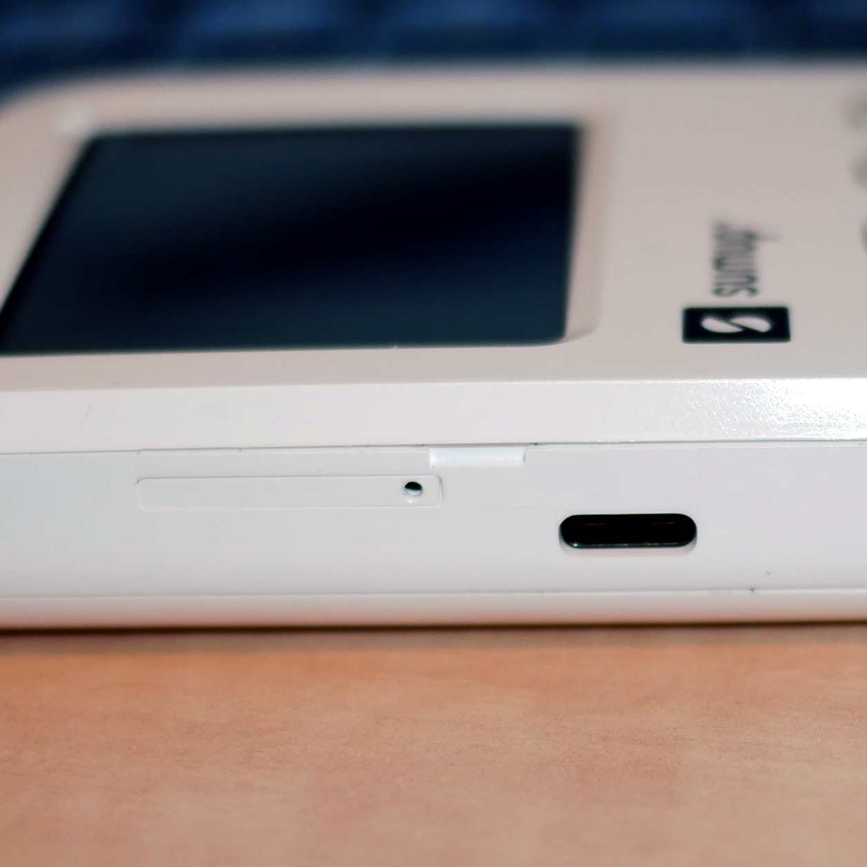
In my opinion this device is booby-trapped. It is built in such a way that there is a user-facing slot that looks very similar to the slot we know from almost every smartphone produced in the past decade. It is a plastic tray with a small hole. The hole can be used to insert a paperclip so that the tray can be ejected. And indeed, the tray is a sim-card slot. However: inserting a paperclip in the hole instantly renders your device useless. 

As soon as you insert a paper clip a tamper mechanism is triggered. This mechanism supposedly erases some battery-backed secure storage or burns fuses. Either way the device will not boot and SumUp will void your warranty. 

Having this slot in here raises the question: if the slot renders the device unusable, why is it even there? Because if the slot would be populated by an employee before the battery is connected for the first time, the back cover is off. So inserting a sim in an internal slot/motherboard slot would be perfectly feasible in that case. 

And even if there would be a valid reason (for example: the anti tamper mechanism is only armed after the device is powered up. The device is assembled in a single location. Local distributors put in the sim cards and seal up the packaging of the product) I can't help but wonder why there isn't a sticker over the sim slot (or the hole) that tells the user:

"Removing the sim tray will trigger the tamper detection system in this device". 

That would have been grand, SumUp. None of the booklets in the packaging seem to mention this. Some people might even think this is a "factory reset" hole. And press it because their device is malfunctioning or they want to sell it to someone else.

Other people on the internet have reported that not charging the device for an extended period of time (like: 6 months?) may trigger one of the tamper detection mechanisms, as well as shocks (due to accidentally dropping the device for example). In all of these cases you're SOL. SumUp has no interest in refurbishing/repurposing these devices and they will not give you a discount for sending it back. 

Repurposing the hardware is pretty difficult since most of the parts that can be easily disassembled have no data sheets or mentions at all on the internet. 

Disassembly and teardown

Since I think I got my point across I guess the only thing left to do is share some teardown pictures! 

To disassemble your SumUp 3G payment terminal start by unscrewing the two screws on the back of the device. Then slide the back cover downwards. You don't have to apply a lot of force to do this. I broke one of the legs because I was pulling on the cover.

Modem and battery


The Quectel modem with
some redacted unique numbers. 
You will be greeted by a cellular modem, in my case a Quectel EG91-EX. This is an LTE (4G) modem with a USB 2.0 interface. The modem in question isn't very special, it is able to do 10mbps down and 5mbps up on LTE and it's an LTE CAT 1 IoT module. The flex cable connects the modem to the mother board and also carries the sim card signals (since the sim card slot is on the mother board). 

Interestingly this device can do way higher speeds (according to the product brochure) when it's used on a DC-HSPA+ network (42mbps down, 5.76mbps up). If I recall correctly this is what we used to call 3.5G.

Next up is the battery, which can be easily removed. Just unclip the connector from the motherboard. The battery is an Amperex Technology PS-GB-304583-010H. It's a 1200mHh (4.44Wh) Lithium Ion cell and it's pretty thin! 


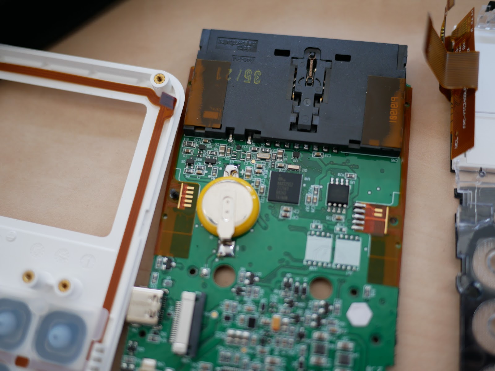
Motherboard back side

From here on I forgot to take a few pictures, but since the device is useless at this point anyway I don't think anyone really cares about how it was disassembled any way.

This is most of the "back" side of the motherboard (the side that you see if you lift the back cover off). One of the most interesting things I noticed is that there is an ESP-WROOM-02U for the WiFi connectivity. I wouldn't have expected to see such a ubiquitous device in a "secure design" like this. Seems like an easy attack vector in a payment system. 

There also seems to be a separate bluetooth chip, a TAIYO YUDEN EYSHCNZXZ Bluetooth 4.2 Low Energy module. These seem to be based on nRF chips by Nordic.

On the left we can see a battery (cell with the yellow insulation) that is presumably used to keep the CPU awake so it can trigger the tamper detection if the Lithium Ion battery is fully depleted.

Main CPU (+ bootloader diagnostics)

The main CPU seems to be a MAX32552 which is a "DeepCover Secure ARM Cortex-M3 Flash Microcontroller". Among the chip features we can see:
  • 6 External Tamper Sensors with Independent Random Dynamic Patterns
  • 256-Bit Flip-Flop-Based Battery-Backup AES Key Storage
  • Temperature and Voltage Tamper Monitor
  • Secure Boot Loader with Public Key Authentication
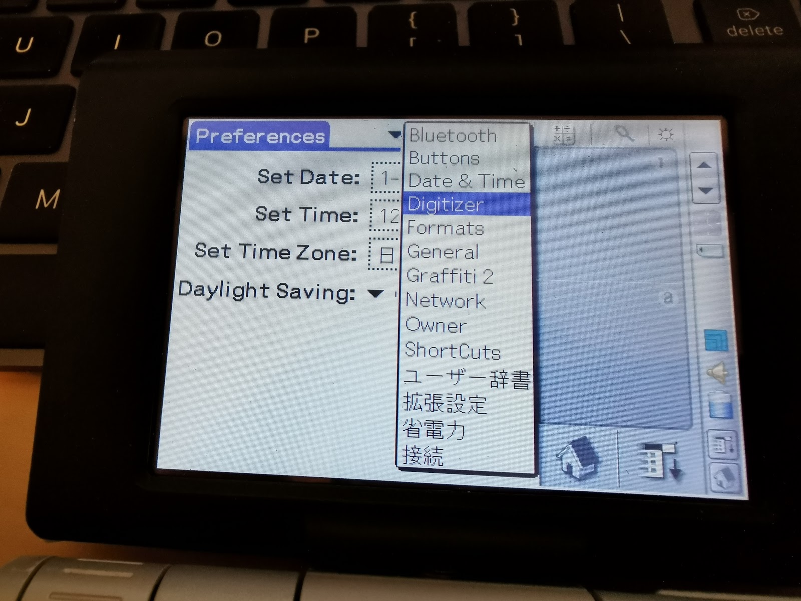
Cool, so that probably explains the D0 to D5 on the "failure diagnostics" screen that you can get in to by pressing "3" on the "Device Blocked" screen. I remember that D1 was the Sim card holder, so it's possible that SH stands for Sim Holder, but that's just speculation. 

Any "sensor" with an inverted background color has been triggered. I've managed to trigger only four out of the six. So I'm still looking for resources on how to trigger D0 (BT?) and D5 (BH?). 

Furthermore we now speculate that as soon as any tamper sensor is triggered the AES key storage is cleared which prevents the device from booting at all (since it's using Secure Boot). This also explains why SumUp can't re-use the motherboard after any of the mechanisms are triggered. 

Below the triggered sensors on the display we can see the date and time that the CPU was rendered useless. This is the time when the first sensor was triggered. Any additional triggers will not update the date and time. 

Card reader tamper shield

There is also a tamper shield around the card reader module. It's a very interesting mesh that prevents any poking around. The foil seems to be sticked to a plastic frame and I noticed some air bubbles between the foil and the plastic frame. In addition I saw a bit of damage to the foil at the bottom part that was already present when I opened the device. 

The idea with these meshes is that the traces all conduct electricity. As soon as the resistance across the mesh changes, the tamper mechanism triggers. I wonder if a big magnet would be able to trigger this mechanism as well. 

Underneath the shield we can see the actual card reader. I couldn't find a model number on the black housing.

Here we can also see the gold fingers (five on the left, two on the right) that connected to the underside of the card reader tamper shield. The underside of the tamper mesh has zebra strips. 


Other parts

The flex-board chip that probably drives
 the touch screen input.
FPC-MTP240-014DAAMFIL


Part number on the flex cable that carries display
signals
YTC240DLBU-02-300C0V3

Other side of the display signal flex cable:
FPC-YTC2400DLBU-02-200N

Conclusion

I'm a bit disappointed that SumUp doesn't make customers aware of the tamper detection mechanism and the kind of things that can trigger it. People these days have put a SIM card in their smartphone at least once in their life or they have seen people do it for them. Curiosity isn't a bad thing. And I'm completely fine with SumUp deciding "if you tamper with our device, we will void the warranty". But please, pretty please: be upfront in what kinds of actions can trigger the tamper detection mechanism.

This is a mobile payment device. Customers will have this device in their hands if they insert their payment card in the bottom and obviously every now and then a device is dropped. That's unfortunate, but nothing that a refurbishment couldn't solve. 

Right now, a small business would need to have a second device on standby if they rely on card payments simply because the tamper mechanism might trigger. This second device has to be charged every few months to prevent the device from bricking itself. Imagine a church that has an annual charity sale that is run by volunteers. They decide to use a SumUp device and after the event they store it in a box for next year. Next year the device is bricked because the battery depleted over time. Why isn't the user informed about this tamper mechanism? Why do people have to find out on their own and bear the cost of purchasing another of these booby-trapped devices?

And don't just display some things that can trigger the mechanism on a FAQ page on your website. Place a sticker on the product packaging. Place it over the sim slot. Place it over the screen. I don't care.

Just make sure that people like me (who DO read thesestickers) are aware of the actions that can trigger the tamper detection sensors.

Something like this:

Thursday 3 December 2020

Modifying the Ubiquiti CRM Key to run Cloud Key firmware

This is an extract from the information that I posted on the Ubiquiti forums in this topic. I'd like to be very clear that if you choose to run any of the commands on this page, you are doing this at your own risk. Don't proceed unless you're okay with potentially bricking your device without any way to recover.

Background

I recently got a CRM Point (being well aware that it it not supported anymore by Ubiquiti) and started playing around with it. For the uninitiated: the Cloud Key is an ARM-based small computer that can be powered over POE. It uses the MediaTek mtk7623 SOC and has 2GiB of RAM memory. The point of the CRM Key was to install it at customers networks which allows a sysadmin to remotely manage compatible (Ubiquiti airMAX) network equipment. 

I noticed that the firmware isn't updated that regularly anymore which is sad. Because it has a limited amount of flash memory and any time I run apt-get update && apt-get upgrade -y this fills the read-write partition. 

But most packages are so old that installing (for example) an up to date version of Java will take more than half of the available storage. Of course I had purchased this device because I intended to tinker with it. So I did exactly that. 

First exploration

I installed CRM.mtk7623.v0.6.0.a670e69M.170615.0748.bin on it (to my knowledge this is the latest firmware that was released for this hardware) and was happy to see that a clean install leaves 100% of space on the rw-partition. This got me thinking: if I can install the updated packages in the read-only partition this will leave the read-write partition almost empty! Given that the read-only partition is situated at /dev/mmcblk0p6 I started trying some stuff out: 
root@control-point:/data# dd if=/dev/mmcblk0p6 of=/data/dd.img
2097152+0 records in
2097152+0 records out

1073741824 bytes (1.1 GB) copied, 101.841 s, 10.5 MB/s

root@control-point:/data# dd if=/data/dd.img of=/dev/mmcblk0p6
2097152+0 records in
2097152+0 records out

1073741824 bytes (1.1 GB) copied, 242.271 s, 4.4 MB/s
So writing to the read-only partition directly does not seem to be blocked in any way. After a reboot everything still works just fine! But interestingly enough the partition is 1.1GB while the size of the read-only filesystem as reported by df is only 207MB. This means that there is some potential room for additional tools and packages! 

First attempt at a 'custom rom'

I extracted the squashfs from /dev/mmvblk0p6 onto /data/, then ran mksquashfs on the squashfs-root folder in /data and then I proceeded to dd the resulting squashfs back to /dev/mmvblk0p6. While the filesystem is mostly fine, somehow my root/ubnt user got borked and I can't log in using ssh :(. I can however log in to the AirControl web UI. My theory is that this was an issue caused by the layer _under_ the rw-overlay changing. Therefore the stuff on top became invalid. Trashing the entire rw-layer fixes that. 


How to start modifying your read-only squashfs:
  • ssh to your crm point
  • cd to /data directory
  • apt-get update && apt-get install squashfs-tools
  • unsquashfs /dev/mmcblk0p6
  • Follow the step on this page about the policy.d file
  • Mount /dev, /dev/pts, /proc sections according to the copy-pasta here
  • chroot squashfs-root
  • mkdir /tmp
At this point you can run apt-get commands as if you are actually "running this system". So this includes adding packages, Fixing /etc/apt/sources.list to also contain jessie-backports, updating existing packages. Just make sure that all of this will still fit in the 1.1GB partition that it will eventually need to squeeze in to. In my case I also removed the aircontrol and postgres packages. Then start your cleanup:
rm -rf /tmp
apt-get clean
# Next line makes sure that on factory reset a new SSH key is generated
rm /etc/ssh/ssh_host_rsa_key.pub /etc/ssh/ssh_host_dsa_key.pub /etc/ssh/ssh_host_ecdsa_key.pub /etc/ssh/ssh_host_ed25519_key.pub
rm -rf /usr/sbin/policy-rc.d
history -c
exit #(this is where you leave your chroot)
umount /proc /dev/pts /dev #In my case some of them didn't want to unmount. If this happens, just reboot the CRM point.
mksquashfs /data/squashfs-root root.sqfs
dd if=/data/root.sqfs of=/dev/mmcblk0p6
From this point on any command you run will likely fail because the rofs was overwritten while mounted. This confuses the system which is understandable. So just pull the power, plug it in again, and attempt to reset the device with a paperclip or something. It should boot up pretty fast and you are now running your custom squashfs image!

Next steps

So given that I was able to modify my squashfs I started to wonder... What if I could extract the kernel and rootfs from the cloud key firmware update and copy it to the flash of my CRM Point using DD? Would the kernel crash? Would the bootloader do some checksum check on the kernel partition? I didn't know, but I wanted to try. Especially since a lot of people on the forum over the years have said "you can't", "you'll brick it" and things like that. And I am pretty stubborn. 

 So first I tried to cross-flash the Cloud Key the firmware using ubnt-systool fwupdate but that failed. This is because the tool that checks which product this is probably uses data from one of the partitions that I didn't touch. But that's actually perfect because I wouldn't want an accidental update to brick my hacked cloud key, so I guess this worked out just fine. 

 1. Determine flash layout

So as most people probably already know, embedded devices running linux usually have multiple partitions. In order to do some analysis on firmwares the tool dd is very useful to make backups of partitions so that if you screw up but you can get the device to boot to some kind of recovery you can restore it. So let's take a look at the partitions:
root@control-point:~# parted /dev/mmcblk0
GNU Parted 3.2
Using /dev/mmcblk0
Welcome to GNU Parted! Type 'help' to view a list of commands.
(parted) p
Model: MMC 004GE0 (sd/mmc)
Disk /dev/mmcblk0: 3937MB
Sector size (logical/physical): 512B/512B
Partition Table: gpt
Disk Flags:


Number  Start   End     Size    File system  Name      Flags
 1      262kB   786kB   524kB                uboot
 2      786kB   1049kB  262kB                config
 3      1049kB  1311kB  262kB                factory
 4      1311kB  34.9MB  33.6MB               kernel
 5      34.9MB  68.4MB  33.6MB               recovery
 6      68.4MB  1142MB  1074MB               rootfs
 7      1142MB  2753MB  1611MB  ext4         appdata
 8      2753MB  3937MB  1185MB  ext4         userdata
As we can see there are quite some partitions. Let's back them all up first. 

 2. Back up all partitions

This makes a copy of every individual partition on to your SD card (which should be mounted at /data)
root@control-point:~# dd if=/dev/mmcblk0p1 of=/data/mmcblk0p1.img
1024+0 records in
1024+0 records out
524288 bytes (524 kB) copied, 0.0360363 s, 14.5 MB/s
root@control-point:~# dd if=/dev/mmcblk0p2 of=/data/mmcblk0p2.img
512+0 records in
512+0 records out
# repeat for every partition number (so till mmcblk0p8)
Next I copied these files from the SD card to my NAS, but of course just putting the SD-card in a SD-card reader is also perfectly fine.

root@control-point:/data# scp mmc* root@192.168.1.13:/mnt/user/FliX/Ubiquiti/
The authenticity of host '192.168.1.13 (192.168.1.13)' can't be established.
ECDSA key fingerprint is c4:0f:f2:89:57:df:bb:85:ee:ba:fb:41:e6:d3:90:9e.
Are you sure you want to continue connecting (yes/no)? yes
Warning: Permanently added '192.168.1.13' (ECDSA) to the list of known hosts.
root@192.168.1.13's password:
mmcblk0p1.img                               100%  512KB 512.0KB/s   00:00
mmcblk0p2.img                               100%  256KB 256.0KB/s   00:00
mmcblk0p3.img                               100%  256KB 256.0KB/s   00:00
mmcblk0p4.img                               100%   32MB   8.0MB/s   00:04
mmcblk0p5.img                               100%   32MB  10.7MB/s   00:03

 3. Examining the DD-images and the firmware files

For this I used the tool binwalk. This walks through a firmware image and looks for certain signatures that are known to identify certain 'parts' of a firmware image. So first I did this for the latest firmware updates for the UCK and CRM Point:

$ binwalk UCK.mtk7623.v1.1.13.818cc5f.200430.0950.bin

DECIMAL       HEXADECIMAL     DESCRIPTION
--------------------------------------------------------------------------------
0             0x0             Ubiquiti firmware header, header size: 264 bytes, ~CRC32: 0x8ED3EC98, version: "UCK.mtk7623.v1.1.13.818cc5f.200430.0950"
260           0x104           Ubiquiti partition header, header size: 56 bytes, name: "PARTkernel", base address: 0x00000000, data size: 0 bytes
324           0x144           uImage header, header size: 64 bytes, header CRC: 0x3960E04E, created: 2020-04-30 10:00:43, image size: 7079048 bytes, Data Address: 0x80008000, Entry Point: 0x80008000, data CRC: 0x7D24D70D, OS: Linux, CPU: ARM, image type: OS Kernel Image, compression type: none, image name: "Linux-3.10.20-ubnt-mtk"
14642         0x3932          xz compressed data
14863         0x3A0F          xz compressed data
7079436       0x6C060C        Ubiquiti partition header, header size: 56 bytes, name: "PARTrootfs", base address: 0x00000002, data size: 0 bytes
7079500       0x6C064C        Squashfs filesystem, little endian, version 4.0, compression:gzip, size: 349822683 bytes, 29395 inodes, blocksize: 262144 bytes, created: 2020-04-30 10:00:22


$ binwalk CRM.mtk7623.v0.6.0.a670e69M.170615.0748.bin

DECIMAL       HEXADECIMAL     DESCRIPTION
--------------------------------------------------------------------------------
0             0x0             Ubiquiti firmware header, header size: 264 bytes, ~CRC32: 0x604E5185, version: "CRM.mtk7623.v0.6.0.a670e69M.170615.0748"
260           0x104           Ubiquiti partition header, header size: 56 bytes, name: "PARTkernel", base address: 0x00000000, data size: 0 bytes
324           0x144           uImage header, header size: 64 bytes, header CRC: 0xE24B3D5A, created: 2017-06-15 14:57:10, image size: 6586640 bytes, Data Address: 0x80008000, Entry Point: 0x80008000, data CRC: 0x2526FE9E, OS: Linux, CPU: ARM, image type: OS Kernel Image, compression type: none, image name: "Linux-3.10.20-ubnt-mtk"
14642         0x3932          xz compressed data
14863         0x3A0F          xz compressed data
6587028       0x648294        Ubiquiti partition header, header size: 56 bytes, name: "PARTrootfs", base address: 0x00000002, data size: 0 bytes
6587092       0x6482D4        Squashfs filesystem, little endian, version 4.0, compression:gzip, size: 216177339 bytes, 17413 inodes, blocksize: 262144 bytes, created: 2017-06-15 14:56:50
So clearly the first 'segments' are ubiquiti specific. Then at offset 324 we see the declaration of a 7079048 byte image. Given that the read-only filesystem is a lot larger than 7 Megabytes this is probably the kernel. The last entry in the table is the actual squashfs filesystem. And this is where it gets interesting! 

 4. Testing a theory 

So let's assume that the images in the firmware update files are being copied 1:1 to the partitions (so: kernel part goes to mmcblk0p4, rofs goes to mmcblk0p6) and no other security/encryption happens in that process. That would mean that we can test this theory by comparing the kernel partition image we created on the CRM Point to the kernel partition image in the firmware update file. dd if=CRM.mtk7623.v0.6.0.a670e69M.170615.0748.bin skip=324 count=6586704 iflag=count_bytes bs=1 of=extracted_crm_kernel So let's test that theory. So we're copying data starting at offset 324 (where the uImage header starts) and we take image size + header size as the count argument. Comparing the extracted_crm_kernel file to mmcblk0p4.img confirmed my suspicion. The only difference between the two files is that the partition we extracted from the CRM is filled with zero's where the kernel data ends. For obvious reasons the firmware update does not contain all the 0's. We're going to take a wild guess and assume that this is also the case for the data partition:

dd if=UCK.mtk7623.v1.1.13.818cc5f.200430.0950.bin skip=324 count=7079112 iflag=count_bytes bs=1 of=extracted_uck_kernel
dd if=UCK.mtk7623.v1.1.13.818cc5f.200430.0950.bin skip=1769875 bs=4 of=extracted_uckrootfs.squashfs

5. Crafting our update file

Earlier in this post thread I showed that using dd to overwrite a partition works just fine, but everything that reads from the partition (especially the overlay one) is screwed up because the underlying data is completely different. Unfortunately swapping a kernel and not the filesystem may also result in a brick. But the kernel and rootfs partitions have a recovery partition in between. Initially I wanted to make a single file that we can write with dd that includes the kernel, recovery and rootfs partitions. But I took a quick peek in mmcblk0p5.img and realised this partition is filled with zeros. This explains why people have no way to recover once they brick this thing :D.

$ cp mmcblk0p5.img extracted_uck_kernel_padded.img # take 32MiB img filled with zeroes
$ dd if=extracted_uck_kernel conv=notrunc of=extracted_uck_kernel_padded.img
13826+1 records in
13826+1 records out
7079112 bytes (7.1 MB, 6.8 MiB) copied, 0.177849 s, 39.8 MB/s
$ dd if=mmcblk0p5.img >>extracted_uck_kernel_padded.img # insert 32MiB of zeroes
65536+0 records in
65536+0 records out
33554432 bytes (34 MB, 32 MiB) copied, 1.16823 s, 28.7 MB/s
$ dd if=extracted_uckrootfs.squashfs >>extracted_uck_kernel_padded.img # then append the squashfs
683248+1 records in
683248+1 records out
349823248 bytes (350 MB, 334 MiB) copied, 11.6135 s, 30.1 MB/s
So next up: copy extracted_uck_kernel_padded.img on to the sdcard so we can flash it! 6. Flashing This is the part where everything either succeeds, or fails. This is your last chance to choose for safety. If you enter these commands and you brick your device, you are on your own. Neither Ubiquiti nor I can provide support to you if this fails. First off, let's determine where we have to write this file to.

root@control-point:/# parted /dev/mmcblk0 'unit s print'
Model: MMC 004GE0 (sd/mmc)
Disk /dev/mmcblk0: 7690240s
Sector size (logical/physical): 512B/512B
Partition Table: gpt
Disk Flags:

Number  Start     End       Size      File system  Name      Flags
 1      512s      1535s     1024s                  uboot
 2      1536s     2047s     512s                   config
 3      2048s     2559s     512s                   factory
 4      2560s     68095s    65536s                 kernel
 5      68096s    133631s   65536s                 recovery
 6      133632s   2230783s  2097152s               rootfs
 7      2230784s  5376511s  3145728s  ext4         appdata
 8      5376512s  7690206s  2313695s  ext4         userdata
Ok, cool. So because we have an image file that spans kernel (32MiB), recovery (32MiB) and rootfs (the rest) we can just tell dd to start writing at offset 2560 until we reach the end of the file. This works because the new rootfs is larger than the previous one. Otherwise it would have been wiser to append some more 00's at the end of our image just to make sure we don't have weird garbage at the end of our actual partition data.

root@control-point:/# dd if=/data/extracted_uck_kernel_padded.img of=/dev/mmcblk0 \
  seek=2560
814320+1 records in
814320+1 records out
416932112 bytes (417 MB) copied, 60.8669 s, 6.8 MB/s

So from this point your stick will be a little confused. SSH logins might fail, and that kind of good stuff. For me just a normal paperclip-reset wasn't enough, I had to do a reset from the web interface as well (or SSH... not 100% sure anymore). But after the reset this thing behaves like a UniFi Cloud Key! Enjoy!


Thursday 6 December 2018

Customise Hue Bulb Startup Behaviour after a power cut


For years people have been wondering why and when Philips would allow users to customise startup behaviour after a power cut. No more! Philips has recently updated the firmware of the bridge and bulbs to allow for a custom power-on behaviour. Unfortunately for now it seems to allow only color temperature (whites) and brightness. But it’s better than nothing!


Open the bridge debug page

  • Open a browser (preferably on a PC or Mac)
  • Go to https://discovery.meethue.com to see the IP address of your Hue bridge (it is called internalipaddress). In my case it is 192.168.1.32
  • Open your favourite browser and enter http://192.168.1.32/debug/clip.html replacing my IP address with the IP you found in the previous step.

    You should see the following page:

Get an API key

If you don’t have an API key yet you can do the following:
  • Replace the default value (/api/1234) with /api
  • Paste the following content in the ‘message body’ field: {"devicetype": "debug_credential" }
  • Press the ‘POST’-button on the web page
  • Run to your Hue Bridge and press the round button on it
  • Press the ‘POST’-button on the web page again
  • Copy the value for “username” to some text editor so you won’t lose it. This value represents your API key.

Identify the lights to modify

In the URL field of the debug page you can append your username, for example /api/0123456789012345678901234567 if your api key is 0123456789012345678901234567.

Next you can get a list of lights by appending /lights to the URL. Then you can press the GET button.

Every light that allows custom startup behaviour will have a startup key in the config property (see image below).

Write down all the ID’s of the lights that you want to modify and that allow custom startup behaviour.

Example showing that the light with ID 1 allows custom startup configuration. You can also see 2, which shows the ID of the second light in the response.

Modify the lights

Append the ID of the light you want to customise to the URL. As a sanity check, press the GET-button and verify that you get the status of the light in the response (no errors).

Paste the following in the Message Body field:
{
  "config": {
    "startup": {
      "mode": "custom",
      "customsettings": {
        "bri": 254,
        "ct": 500
      }
    }
  }
}
  • Adjust the Bri (Brightness, 0-255) and CT (Colour Temperature, ranging from 153 (6500 Kelvin, bright white) to 500 (2000 Kelvin, warm white).
  • Press the PUT button
  • Repeat for the other lights
Now to verify that it works, turn off the physical power switch to your light, wait for approx 5 seconds, and flip the switch again. Enjoy!